![]()
Come fly with us today !

Come fly with us today ! |
|
|
|
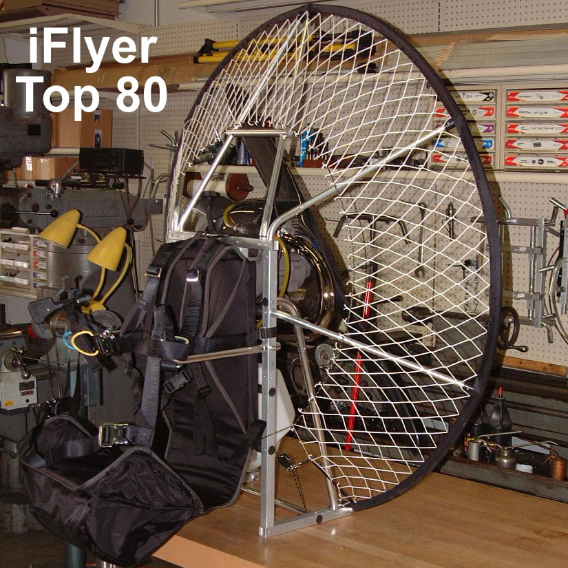
iFlyer Top 80
PJ enjoys his iFlyer!
|
Top 80 Weight 42lb
|
The iFlyer is a simple, low cost paramotor. It utilizes a riveted aluminum frame which can be built by the pilot, or purchased already built. Once built, it can be easily disassembled to fold into the trunk of your car.
The iFlyer is lightweight, using the time tested Top 80 motor built in Italy. It comes with a wooden prop that can be upgraded to a carbon fiber propeller at an additional $200.
The iFlyer is made for pilots up to 200 lbs that prefer to use a lighter paramotor, depending more upon their launch skills and flying habits than the raw power from a heavier paramotor.
The iFlyer weighs 41 lbs. dry, and is a joy to walk around, launch and fly with
CENTRIFUGAL
FRICTION CLUTCH
TOP 80 MINI-MOTOR
LARGE DIAMETER PROPELLER
REDUCTION
ENGINE COOLING
THROTTLE CONTROL
WALBRO CARBURETOR
|
This is not something you will have to do very often, probably only after 250hrs or more. Just as well as it’s a gooey dirty job involving extremes of temperature and clouting things with a big hammer. Appendages ARE at risk! Having said that, it’s a straightforward operation and inexpensive to boot. (At least for the grease version described here, where the 4 bearing replacement set comes to R120 inclusive. The oil version bearings cost much more for some odd reason). This sequence is for the grease filled version and may be similar for the oil version as well as for other similar reduction boxes e.g. The ROS125, where this can be used as a rough guide.
Excessive leakage at the seals – This is one of the reasons I did this overhaul, although more of a nuisance factor than anything dangerous, you don’t want leaked grease to accumulate in the clutch housing and get on the clutch!
Excessive play at prop tips – This was the main reason why I did the overhaul, which turned out to not have been necessary after all! I will explain later. If you have play at the prop tips, first check the prop hub to shaft fit. There should be no play here whatsoever! When fitting the prop hub, the mating splines should be spotless and at least one non-deforming large flat thick stainless washer (I use three) used to distribute the load from the fixing screw. I even smeared the splines liberally with red locking compound the first time round, although I would suggest NOT doing this as I nearly destroyed the aluminum prop hub with a gear puller and heat, trying to get it off again!! It also took a further hour just to clean the gunk off the splines and get them spotless again. You don’t want to run the motor with a loose prop hub, the steel shaft splines will chew up the aluminum hub in no time. What can cause this is if the washers are too few/thin, they become dished under the force of the bolt, the bolt loosens, and the hub starts rocking and loosening on the shaft. This is BAD and will cost a new hub if allowed to continue!
Having gotten this important check out of the way, if you feel that the prop tip play is excessive, feel free to follow this guide. What is excessive? I had about 5mm in the 6/12 o’clock prop position and 2mm in the 3/9 o’clock position. I attributed this to more force in the 6/12 o’clock position due to the motor pitching while running for takeoff. I haven’t got my head round the fact that this pitching should be manifesting itself as wear in the 3/9 o’clock position due to gyroscopic precession, so ignoring the facts, lets continue on blindly. I thought this play was excessive but guess what? After the overhaul, I ended up with 5mm ALL round!! I was quite disappointed in this and blamed the back prop-shaft bearing which did seem a bit looser than the others when I put it in. Turns out to be not such a big deal after all. Diego, the Top80 manufacturer says that some play is normal and 2-3mm play at the prop tip equates to so much less at the bearing itself due to the multiplier effect of the prop length. Well, I have flown about 5 hrs with this play on the new bearings and the box is running smooth as ever, so I guess the play a non-issue in this case.
Strange noises – Any clicking or grinding is a bad thing obviously! Check and eliminate the clutch first (you are going to expose the clutch while removing the gearbox anyway). With the gearbox off the motor, check for grease oozing out between the clutch bell and the housing, try to turn and rock the clutch bell to check for play or roughness. Do the same for the output (prop) shaft. Any of the above is a good reason to get down and dirty with the ‘box.
1) Bearings (all RS – rubber sealed both sides):
1 X 6003
1 X 6202
2 X 6002
2) Gasket sealant.
3) LM Grease.
4) Assorted tools, pullers, drifts, hammers etc.
5) Long bolts to fit casing for separation only.
6) Mini blow torch/oven and freezer.
7) Cleaning rags (plenty).
8) Thread-locking compound.
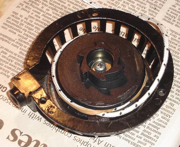
Here is a pictorial guide of what to do:
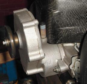 1)
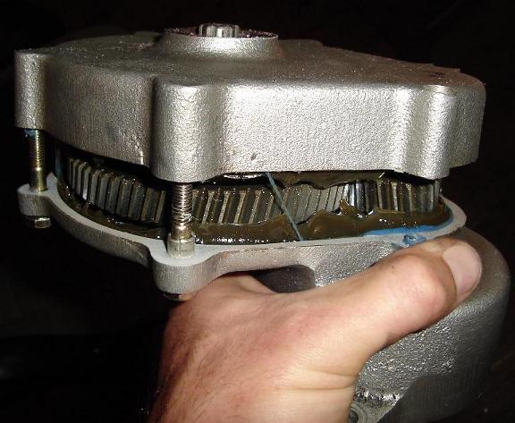
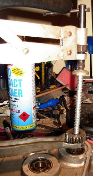
This is what the reduction box looks like prior to removal. Note the
3 thick washers under the prop hub hold down bolt. Remove the bolt and
washers. Remove the nuts on either side of the clutch housing and take the
whole re-drive unit off.
1)
This is what the reduction box looks like prior to removal. Note the
3 thick washers under the prop hub hold down bolt. Remove the bolt and
washers. Remove the nuts on either side of the clutch housing and take the
whole re-drive unit off.
2)
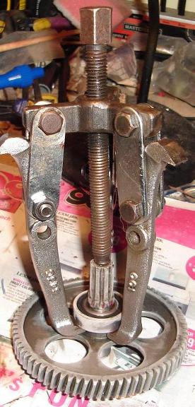
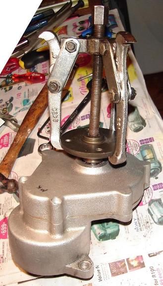 Use
a puller to remove the prop flange.
Use
a puller to remove the prop flange.
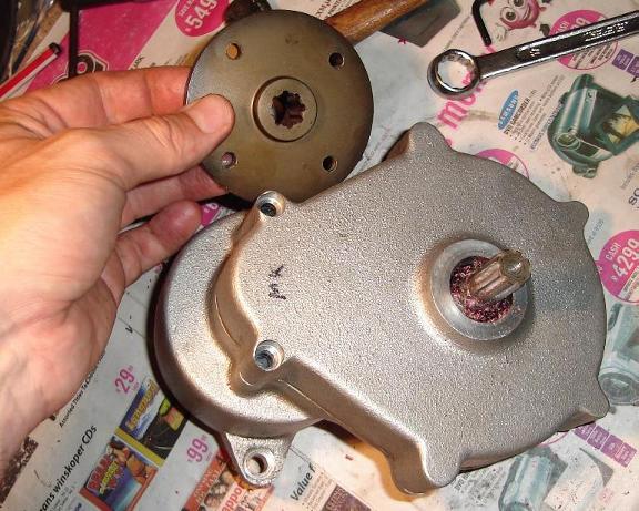 3)
Here you can see the undamaged mating surfaces between hub and
shaft. The red flakes around the shaft are thread-lock shavings, which had
to be meticulously cleaned off. I don’t recommend applying thread-lock in
this way unless you have a badly fitting hub due to previous wear. Note my
initials on the box, just in case I forget whose it is! I think having to
mark my schoolbooks and lunchboxes may have affected me for life!!
3)
Here you can see the undamaged mating surfaces between hub and
shaft. The red flakes around the shaft are thread-lock shavings, which had
to be meticulously cleaned off. I don’t recommend applying thread-lock in
this way unless you have a badly fitting hub due to previous wear. Note my
initials on the box, just in case I forget whose it is! I think having to
mark my schoolbooks and lunchboxes may have affected me for life!!
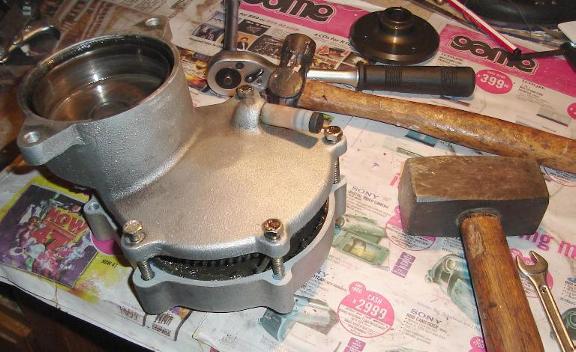
 4)
Here we are fitting the four long bolts, which will allow us to
separate the two halves of the case. Note the excessive grease oozing past
the clutch bell, one of the reasons why I decided to change out the
bearings. The double set of clutch bell side bearings contained rubber
seals on one of the bearings only (the outermost one). I’m leaving all
seals in place to stop this leakage on the new clutch shaft bearings.
There should not be a problem doing this, as the bearings are supposedly
pre-lubed for life. Any leakage out of the clutch bell side should be
matched by leakage in from the gearbox side, resisted by four seals rather
than just two. Time will tell if this is an improvement.
4)
Here we are fitting the four long bolts, which will allow us to
separate the two halves of the case. Note the excessive grease oozing past
the clutch bell, one of the reasons why I decided to change out the
bearings. The double set of clutch bell side bearings contained rubber
seals on one of the bearings only (the outermost one). I’m leaving all
seals in place to stop this leakage on the new clutch shaft bearings.
There should not be a problem doing this, as the bearings are supposedly
pre-lubed for life. Any leakage out of the clutch bell side should be
matched by leakage in from the gearbox side, resisted by four seals rather
than just two. Time will tell if this is an improvement.
5) The four bolts in place, screwed in as far as possible for maximum thread contact. Don’t force them in too far and strip the threads though. Supporting the box by the clutch (i.e. Suspending the lower part of the box in the air) tap down successively on each of the four bolts gently to break the seal and separate the case. This should pop apart fairly easily once the seal is broken
 6)
Here, the bolts have been tapped through to their maximum extent and
can be removed. The old grease can be seen, still fairly clean, to be
expected on a low hours box. Looks like a blue silicone based sealant was
used previously see the stringy bit still clinging on between each half of
the case. It did the job; I had no leaks along the join.
6)
Here, the bolts have been tapped through to their maximum extent and
can be removed. The old grease can be seen, still fairly clean, to be
expected on a low hours box. Looks like a blue silicone based sealant was
used previously see the stringy bit still clinging on between each half of
the case. It did the job; I had no leaks along the join.
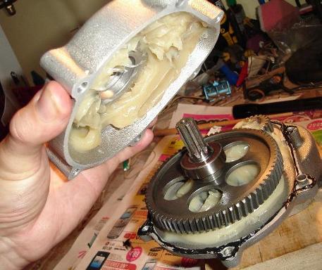
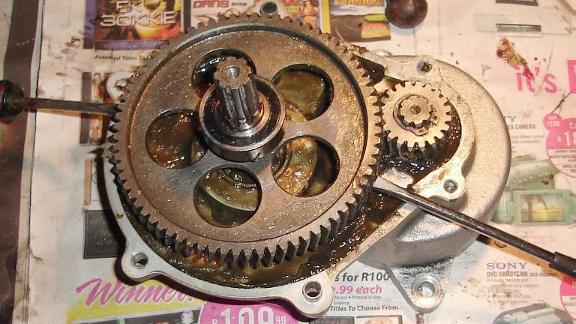 7)
Using two large screwdrivers as levers, the main gear can be levered
out. Be careful not to damage the mating surfaces with the screwdrivers. It
should pop out fairly easily. If not, make sure that the force is applied
evenly to each side and use pieces of wood to lever against to protect the
case.
7)
Using two large screwdrivers as levers, the main gear can be levered
out. Be careful not to damage the mating surfaces with the screwdrivers. It
should pop out fairly easily. If not, make sure that the force is applied
evenly to each side and use pieces of wood to lever against to protect the
case.
 8)
The fun part, cleaning out all the old grease! Remove the circlip
from the small pinion so long.
8)
The fun part, cleaning out all the old grease! Remove the circlip
from the small pinion so long.
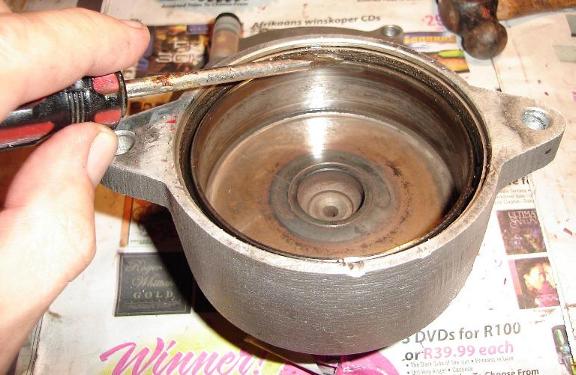 9)
Scribe a line along the top of the clutch bell against the casing.
This will indicate how far the bell/shaft needs to be driven in on
reassembly. Note the small groove in the lower casing flange to let the
excess grease ooze out. It will be an easy inspection point to monitor the
new bearing’s grease retention in future too.
9)
Scribe a line along the top of the clutch bell against the casing.
This will indicate how far the bell/shaft needs to be driven in on
reassembly. Note the small groove in the lower casing flange to let the
excess grease ooze out. It will be an easy inspection point to monitor the
new bearing’s grease retention in future too.
 10)
Here are two parts I had to modify (using a small angle grinder) to
allow removal of the small pinion. The top part is the end of a valve
removal tool; the lower is a coach bolt with its head removed.
10)
Here are two parts I had to modify (using a small angle grinder) to
allow removal of the small pinion. The top part is the end of a valve
removal tool; the lower is a coach bolt with its head removed.
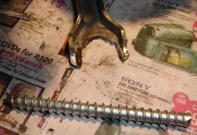
 11)
Here is the custom tool in action. Make sure to remove the circlip
first! Before doing it this way, I had tried to lever the pinion off but
without success. Your mileage may vary so perhaps try levering it off
first, just don’t damage the soft aluminum mating surfaces. Now drive the
shaft out through the two supporting bearings being careful to support the
edges of the clutch housing but allow room for the bell to exit the
housing. This was quite tight and took many blows with the large hammer. I
really though I was going to break something, but that casing is tougher
than it looks.
11)
Here is the custom tool in action. Make sure to remove the circlip
first! Before doing it this way, I had tried to lever the pinion off but
without success. Your mileage may vary so perhaps try levering it off
first, just don’t damage the soft aluminum mating surfaces. Now drive the
shaft out through the two supporting bearings being careful to support the
edges of the clutch housing but allow room for the bell to exit the
housing. This was quite tight and took many blows with the large hammer. I
really though I was going to break something, but that casing is tougher
than it looks.
 12)
Just look at that cool frosty finish on the main gear, makes me want
to reach into the fridge for a cool one…. The gear spent an hour or so in
the freezer to cool it down. I then warmed the bearing with a mini
blowtorch to maximize the temperature differential (and therefore clearance)
prior to pulling the bearing off. It was quite tight. I don’t think you
would be able to lever this one off without the correct tool. Drive a new
bearing on the still chilled shaft using a drift contacting the centre of
the bearing only. I seem to remember using a spark plug socket.
12)
Just look at that cool frosty finish on the main gear, makes me want
to reach into the fridge for a cool one…. The gear spent an hour or so in
the freezer to cool it down. I then warmed the bearing with a mini
blowtorch to maximize the temperature differential (and therefore clearance)
prior to pulling the bearing off. It was quite tight. I don’t think you
would be able to lever this one off without the correct tool. Drive a new
bearing on the still chilled shaft using a drift contacting the centre of
the bearing only. I seem to remember using a spark plug socket.
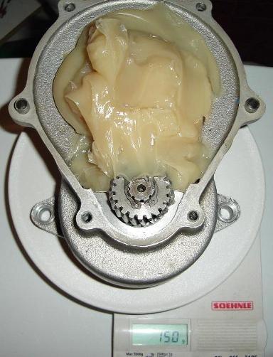 13)
Ok we have jumped ahead a bit here, the old bearings have been
removed by heating the case in the oven to 150 degrees C, and then using
oven mitts, bang out both the clutch bearings and the single prop shaft
bearing onto the kitchen table (protective covering advised). New bearings
from the freezer can be popped in at the same time but be sure to keep them
cool to avoid damaging the seals. The seals should be removed from the rear
prop shaft bearing first. (This is the only one you need to remove seals
from). Drive the (chilled) clutch bell/shaft back into place (up to the
mark previously scribed in the bell housing) once the bearings have reached
room temperature again. Refit the small pinion and circlip. Now measure
out 150g of standard lithium based grease (e.g. Castrol LM). I used a scale
(see below) zeroed (press Tare button) with the weight of the box on it,
then add grease to the 150g mark.
13)
Ok we have jumped ahead a bit here, the old bearings have been
removed by heating the case in the oven to 150 degrees C, and then using
oven mitts, bang out both the clutch bearings and the single prop shaft
bearing onto the kitchen table (protective covering advised). New bearings
from the freezer can be popped in at the same time but be sure to keep them
cool to avoid damaging the seals. The seals should be removed from the rear
prop shaft bearing first. (This is the only one you need to remove seals
from). Drive the (chilled) clutch bell/shaft back into place (up to the
mark previously scribed in the bell housing) once the bearings have reached
room temperature again. Refit the small pinion and circlip. Now measure
out 150g of standard lithium based grease (e.g. Castrol LM). I used a scale
(see below) zeroed (press Tare button) with the weight of the box on it,
then add grease to the 150g mark.
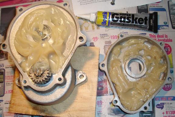 14)
Probably unnecessary, but I distributed the grease between the two
halves. Don’t get it in the bearing seat (right side cover) or it could
promote bearing spin in the housing. See the brand of sealant I used in the
picture below, it’s a black silicone based sealant.
14)
Probably unnecessary, but I distributed the grease between the two
halves. Don’t get it in the bearing seat (right side cover) or it could
promote bearing spin in the housing. See the brand of sealant I used in the
picture below, it’s a black silicone based sealant.
 15)
A thin bead of sealant has been applied to the mating surfaces and
the two halves are brought together. If your prop-shaft output bearing was
subject to spinning in it’s housing, apply thread-locker compound around the
seat area first.
15)
A thin bead of sealant has been applied to the mating surfaces and
the two halves are brought together. If your prop-shaft output bearing was
subject to spinning in it’s housing, apply thread-locker compound around the
seat area first.
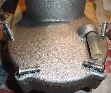 16)
Note that the two shorter screws are closer in the picture left.
Note the missing black vent cap cover, it melted in the oven, oops!! (I have
since procured a toothpaste cap drilled 1.5mm in the centre, hot glued on,
which is working admirably so far).
16)
Note that the two shorter screws are closer in the picture left.
Note the missing black vent cap cover, it melted in the oven, oops!! (I have
since procured a toothpaste cap drilled 1.5mm in the centre, hot glued on,
which is working admirably so far).
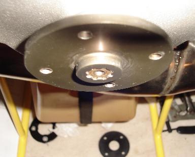 17)
Refit the box and drift on the prop hub, making sure the shaft and
hub contact surfaces are spotless. There should be no rocking and the shaft
should sit in 1-2mm as shown in the picture below to allow the retaining
bolt to draw down. Apply a little thread-locking compound to the screw and
tighten up, using 2-3 thick washers. Be careful not to bottom the screw if
it’s too long.
17)
Refit the box and drift on the prop hub, making sure the shaft and
hub contact surfaces are spotless. There should be no rocking and the shaft
should sit in 1-2mm as shown in the picture below to allow the retaining
bolt to draw down. Apply a little thread-locking compound to the screw and
tighten up, using 2-3 thick washers. Be careful not to bottom the screw if
it’s too long.
18) Refit the prop and off you go!
HAPPY REDUCTIONS.
Regular maintenance of your pull-start system can save you from missing perfect flying opportunities, and your engine from ingesting unwanted parts. The overhaul sequence described here involves replacing the starter cord (which should be done as a matter of course whenever the starter is serviced) and a lubrication service of various related components.
On the Top80 Miniplane, this entails separating the engine from the frame by undoing 4 screws and removing the pull-start spool’s 3 screws. There is no riveting work required for this procedure and it should take no longer than 2 hours to complete. The procedure should be similar on other forced air-cooled motors like the Ros125.
It is especially important to maintain the pull-start on a regular basis when flying at the coast due to the large volumes of moist salty air drawn through the starter system by the engine fan to cool the engine’s cylinder and head. I would expect that a once a year preventative service should be sufficient with regular weekly use.
Frayed starter rope – could break soon
Rope fails to retract – spool return spring getting rusty and sticking or some other obstruction
Hard to pull – (assuming no other engine problem like seizing), spool spindle or rope pulley needs lubrication, insufficient rope on pulley
Fails to engage – Plastic starter pawls seizing on standoff posts. This is especially bad if one or two of the three pawls seize, causing the load to be taken up by the remaining pawl(s) which can cause further damage (see ‘strange noises’ below)
Strange noises – The pawls could have started disintegrating already. Further damage could be caused by ingestion of pawl parts into the engine fan. The remaining pawl standoffs may have been bent by the additional load placed on it causing the pawl to rub on the cover or be broken off. Fan damage/breakup is possible, stop the engine immediately and inspect for damage
Here is a pictorial guide of what to do:
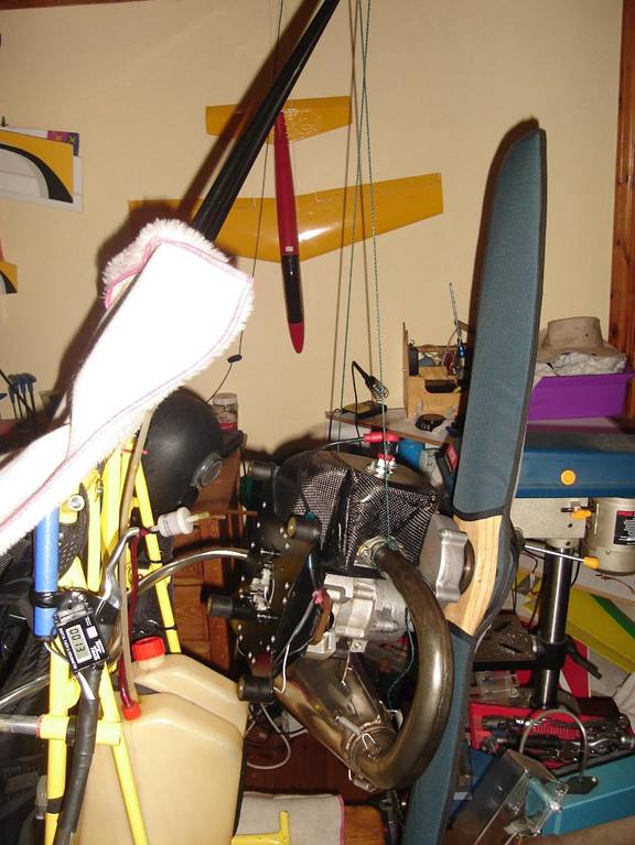
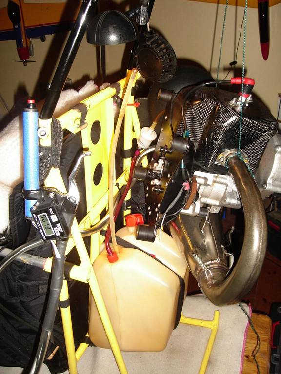
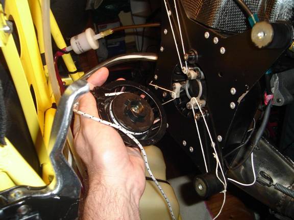
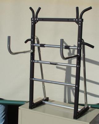
1) Raise the Paramotor onto a low table or chest, so that it can be worked on at eye level or slightly below. Tie a rope from exhaust via top of ‘A’ frame prop guard to carb on the other side to support the engine when the mounts are undone. Tension the rope so that it takes the load of the motor (so that the motor doesn’t drop on removing the mounting bolts). Undo the four mounts by removing the screws on one side only. In the picture above, you can see the 4 rubber mounts still attached to the engine size, the screws having been removed from the frame side. The complete motor unit will now swing away from the frame enough to get at the pull start mechanism.
2) Be careful to relieve any tension on the fuel line and throttle cable. They should not need disconnecting though.
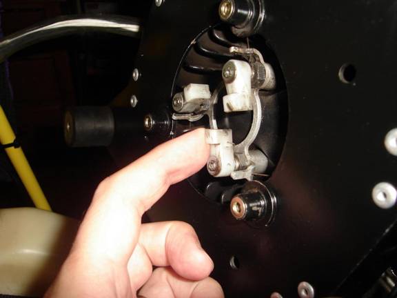
3) Remove the three screws holding the starter pulley cover onto the engine. The white plastic pawls should now be exposed. Check that they are undamaged and that the posts are straight. The pawls should return easily if tensioned against the springs. These were starting to stick. Lubricate the posts so that the pawls move as freely as possible and wipe off the excess.
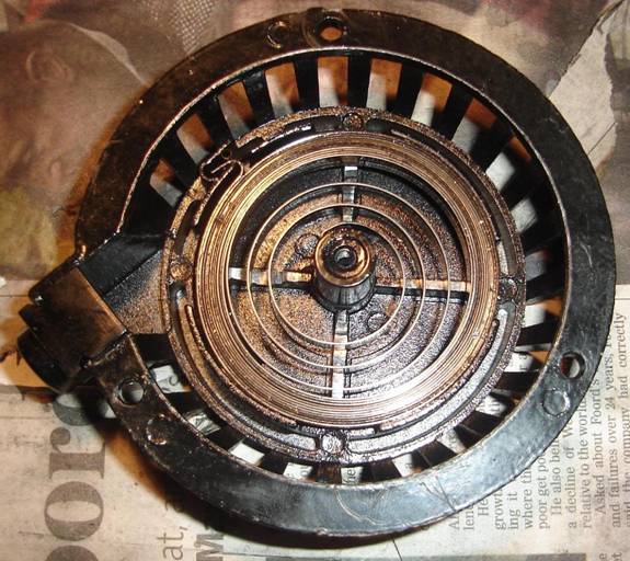
4) Here is the source of my retracting woes. The rope failed to retract fully as the spring was starting to corrode and stick together. I used WD40 and a flat blade screwdriver slid all along between the leaves of the spring to free it up. Note the abnormal wear on the left side of the ‘+’ guide. I also noted quite a bit of wear on one side of the centre spindle due to lack of lubrication. This caused about 1mm play on reassembling the spool later. Neither of these caused an issue with the spool operation on re-assembly, but left unchecked, who knows…
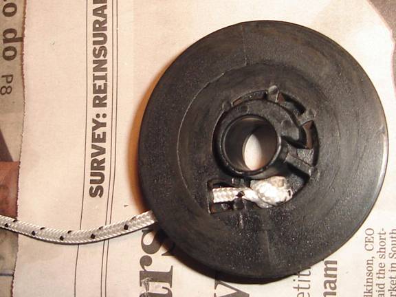
5) Here, we are rewinding the spool with about 1m of special indestructible 3.0mm rope of the ‘Titan’ variety, dyneema inner and outer for maximum strength. Accept no substitute.
6) Re-grease the centre spindle (don’t get it on the rope) and rewind as shown. The rope needs to be no thicker than 3mm to allow sufficient length in the spool for a good pull. It will sit staggered in the groove (not on top of each other). This is normal. The spool should be packed out till just level with the edge to obtain maximum leverage on the initial pull without any binding or jumping off the spool on return. Leave another 50cm or so free to sling around the pulley and attach the handle. Don’t cut off the excess until re-assembly is complete and tested.
7) Time to refit the spool assembly. The pawls need to be held back by some unrestrictive means while refitting. Here I use loops of string, which can be cut and removed later. Only slight tension needs to be maintained on the spool spring, too much and the spring will ‘bottom out’ before the rope is fully extended, too little and the rope will not remain fully retracted against the weight of the handle and could allow the handle to end up in the prop, ouch!
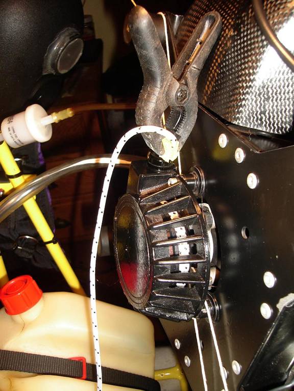
8) Here, I use a clamp as a ‘third hand’ while fastening the three cover screws. Note, there should not be much force on the rope at this point. The spool also looks a little overloaded here but a little rope will be removed on final adjustment at the handle end. The strings can now be cut releasing the pawls against the spool ratchet. Now reconnect the motor to the frame and attached the rope via the ‘A’ frame pulley to the handle, test, adjust and trim the excess once happy. I found the motor much easier to turn over due to the fully packed spindle (more leverage) and lubricated pulley spindle (less drag). The service is worth doing just for that alone even if there is nothing else visibly wrong.
HAPPY STARTING.
Regards,
Markk.

 LIGHTWEIGHT
FRAME
LIGHTWEIGHT
FRAME